|
MatrixMiniR4 1.2.2
Matrix Mini R4 Arduino Library API Documentation
|
|
MatrixMiniR4 1.2.2
Matrix Mini R4 Arduino Library API Documentation
|
Class for handling digital input and output operations. More...
#include <MiniR4Digital.h>
Public Member Functions | |
| MiniR4Digital () | |
| bool | getL (bool pullup=false) |
| Reads the state of the first pin. | |
| bool | getR (bool pullup=false) |
| Reads the state of the second pin. | |
| void | setL (bool level=HIGH) |
| Sets the level of the first pin. | |
| void | setR (bool level=HIGH) |
| Sets the level of the second pin. | |
| void | toggleL () |
| Toggles the state of the first pin. | |
| void | toggleR () |
| Toggles the state of the second pin. | |
Public Attributes | |
| MiniR4HC04< PIN1, PIN2 > | US |
| MiniR4DHT11< PIN1, PIN2 > | DHT11 |
| MiniR4DS18B20< PIN1, PIN2 > | DS18B20 |
| MiniR4_Grove_US< PIN1, PIN2 > | GroveUS |
| MiniR4DHT11< PIN2, PIN1 > | MXDHT |
| MiniR4DS18B20< PIN2, PIN1 > | MXOnewireDT |
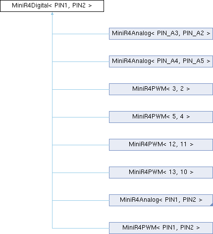
Class for handling digital input and output operations.
This template class provides methods for reading and writing digital signals to two specified pins, along with instantiating various sensor classes that can be connected to these pins.
| PIN1 | The first pin number. |
| PIN2 | The second pin number. |
Definition at line 26 of file MiniR4Digital.h.
|
inline |
Definition at line 29 of file MiniR4Digital.h.
|
inline |
Reads the state of the first pin.
Configures the pin as an input and optionally enables the pull-up resistor.
| pullup | True to enable the internal pull-up resistor, false otherwise. |
Definition at line 43 of file MiniR4Digital.h.
|
inline |
Reads the state of the second pin.
Configures the pin as an input and optionally enables the pull-up resistor.
| pullup | True to enable the internal pull-up resistor, false otherwise. |
Definition at line 61 of file MiniR4Digital.h.
|
inline |
Sets the level of the first pin.
Configures the pin as an output and writes the specified level to it.
| level | The level to write to the pin (HIGH or LOW). Default is HIGH. |
Definition at line 78 of file MiniR4Digital.h.
|
inline |
Sets the level of the second pin.
Configures the pin as an output and writes the specified level to it.
| level | The level to write to the pin (HIGH or LOW). Default is HIGH. |
Definition at line 91 of file MiniR4Digital.h.
|
inline |
Toggles the state of the first pin.
Configures the pin as an output and toggles its current state.
Definition at line 102 of file MiniR4Digital.h.
|
inline |
Toggles the state of the second pin.
Configures the pin as an output and toggles its current state.
Definition at line 113 of file MiniR4Digital.h.
| MiniR4DHT11<PIN1, PIN2> MiniR4Digital< PIN1, PIN2 >::DHT11 |
Definition at line 120 of file MiniR4Digital.h.
| MiniR4DS18B20<PIN1, PIN2> MiniR4Digital< PIN1, PIN2 >::DS18B20 |
Definition at line 121 of file MiniR4Digital.h.
| MiniR4_Grove_US<PIN1, PIN2> MiniR4Digital< PIN1, PIN2 >::GroveUS |
Definition at line 122 of file MiniR4Digital.h.
| MiniR4DHT11<PIN2, PIN1> MiniR4Digital< PIN1, PIN2 >::MXDHT |
Definition at line 125 of file MiniR4Digital.h.
| MiniR4DS18B20<PIN2, PIN1> MiniR4Digital< PIN1, PIN2 >::MXOnewireDT |
Definition at line 126 of file MiniR4Digital.h.
| MiniR4HC04<PIN1, PIN2> MiniR4Digital< PIN1, PIN2 >::US |
Definition at line 119 of file MiniR4Digital.h.